
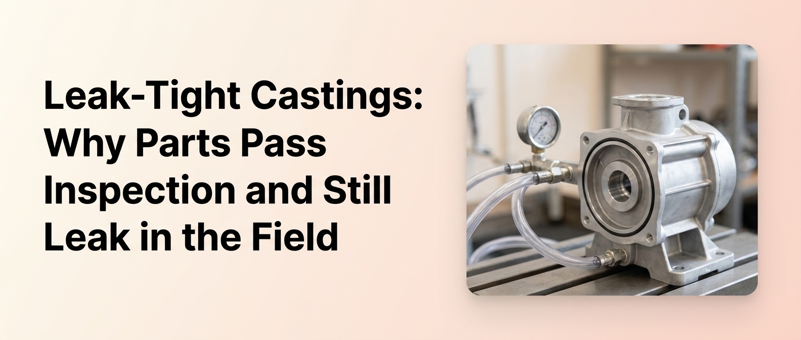
Sourcing leak-critical parts from an aluminium die casting components supplier means dealing with a frustrating reality: castings can clear every inspection at the plant and still leak after machining, assembly, shipping, or real service loading. This guide is built for OEM procurement, quality, and engineering stakeholders who need to understand why that happens and how to prevent it. A die casting passes a leak test only when it meets the specific pressure, medium, temperature, hold time, and part condition of that test – nothing more. Later machining, thermal cycling, vibration, and exposure to actual fluids can open or enlarge leak paths that were absent or undetectable during the original inspection.
Key takeaways
- Passing a pressure or air decay test only proves the part met the tested condition, not every real-world service condition.
- Field leakage often originates in tooling, casting, venting, or process variation rather than inspection alone.
- Machining can open subsurface porosity in a machined sealing face after an as-cast part has already passed earlier checks.
- “Leak-tight” is meaningless in an RFQ unless it defines pressure, medium, allowable leak rate, temperature, hold time, and part condition.
- Vacuum impregnation can seal interconnected micro-porosity where approved, but it does not fix gross defects, cold shuts, or poor design.
- Choosing a supplier with in-house control over tooling, casting, machining, and validation reduces field-leak risk.
What buyers actually mean by “leak-tight” in aluminium die cast components
“Leak-tight” is a specification, not a claim. It only becomes meaningful when tied to measurable test conditions, which is why comparing suppliers on the phrase alone leads to mismatched expectations and field failures.
Leak-tight, in engineering terms, means a part meets a defined maximum allowable leak rate under specified test conditions – test pressure, test medium, temperature, hold time, and part condition. There is no universal “leak-tight”; a tolerance should read as a specified air leak rate at a specified test pressure and duration.
To define leak-tightness credibly, an RFQ should state:
- Test pressure – set against working pressure with a safety factor. General housings may test at 0.1–0.5 bar; hydraulic parts can range from 5 to 350 bar.
- Test medium – dry air, nitrogen, or helium for higher sensitivity, with correlation to the actual service fluid understood.
- Allowable leak rate – expressed as volume or mass flow, e.g. cc/min at a stated pressure.
- Temperature – usually room temperature, but state the service range where hot fluids are involved.
- Hold time – dwell at pressure long enough to detect slow leak paths.
- Part condition – whether testing is done as-cast or after machining.
Leak-tight vs. pressure-tight vs. porosity-free – what’s the difference?
These terms are often used interchangeably, but they are not equivalent. “Pressure-tight” describes a part that retains pressure under a defined load. “Leak-tight” is the quantified version of that – a specific leak rate at specific conditions. “Porosity-free” is misleading: no high-pressure die casting is genuinely free of porosity. Every casting contains some level of gas or shrinkage voids. The functional goal is not zero porosity but reliable pressure retention, where any porosity present does not form a continuous leak path through the wall.
Why a casting can pass inspection and still leak in service
A passed test is a snapshot. It confirms the part behaved acceptably under one set of conditions at one point in time – and nothing about how it will behave after downstream processing or in the field.
Aluminium die cast parts can pass inspection yet leak later because the part changes after testing. Machining exposes subsurface porosity, assembly loads seals and threads, and service introduces thermal cycling, vibration, and real fluids. A short gas leak test does not replicate long-term fluid performance under these conditions.
The typical failure timeline runs like this: the part passes at inspection, then goes through machining that removes the dense as-cast skin, then assembly that loads sealing faces and threads, then shipping and handling, then installation, and finally real service loading – thermal expansion, vibration, and pressurised media. A leak can appear at any of these stages even though the earlier test result was genuine.
The Metal Casting Institute notes that long-term performance with fluids, including hot oil, can differ from short-term gas leak tests, and recommends correlation studies between leak tests and downstream assembly tests. Godfrey & Wing adds that liquid leakage and surface tension factors depends on hole diameter, length, surface finish, fluid viscosity, and surface tension – so a leak path that passes an air-based test may still pass fluid under service conditions. This is why leak-tightness has to be defined and tested against the conditions the part will actually see, not just a convenient bench condition.
Hidden leak paths: porosity, parting lines, cold shuts, and machining breakthrough
Field leakage commonly traces back to a physical defect that forms a continuous path through the casting wall. Understanding these defect types is the difference between chasing symptoms and fixing root cause.
The defects most likely to cause field leakage are gas porosity, shrinkage porosity, interconnected micro-porosity, cold shuts, and parting-line leaks. Machining breakthrough – where cutting exposes subsurface voids – is a common cause of parts that leak only after machining, even when the as-cast part passed earlier checks.
| Failure source | Typical cause | When it appears | Which test may miss it | Prevention method | Supplier question to ask |
| Gas porosity | Trapped air/gas during fill | After machining or under pressure | Basic air decay if internal | Venting, vacuum assist | How is die venting designed and maintained? |
| Shrinkage porosity | Insufficient feed during solidification | Under sustained pressure | Surface bubble test | Gate/overflow design, intensification pressure | How are hot spots and feed paths controlled? |
| Micro-porosity | Fine distributed voids | After machining opens a path | Low-sensitivity tests | Process window control, vacuum assist | What is your leak-test sensitivity? |
| Cold shuts | Incomplete metal fusion | Under thermal/pressure load | Visual-only inspection | Melt and die temperature control | How are melt and die temperatures monitored? |
| Parting line leak | Flash/mismatch at parting line | Assembly / seal load | Dimensional-only checks | Tool maintenance | What is your die maintenance schedule? |
| Machined-through porosity | Machining exposes subsurface voids | Post-machining | Pre-machining leak test | Test after machining | Do you leak test after machining? |
Gas porosity vs. shrinkage porosity vs. micro-porosity
Gas and shrinkage porosity in die castings forms when air or gas is entrapped during die filling. Shrinkage porosity forms when molten metal cannot feed thick sections during solidification. Micro-porosity is fine, distributed voids that individually may not leak but can interconnect into a path.
Gas porosity tends to be rounded and smooth-walled, often near the surface or where gas cannot escape. Shrinkage porosity is irregular and concentrated in thicker sections and hot spots. Micro-porosity is dispersed throughout the matrix and is most dangerous when networks interconnect, since machining can then open a complex leak path that low-sensitivity tests will not catch.
Why parting lines and cold shuts create leak paths
Parting-line leaks come from die mismatch, flash, or misalignment where the two die halves meet. When a sealing face, gasket surface, or O-ring groove crosses a parting line, any step or damage there can let fluid pass around the seal even when the casting body is internally sound. Cold shuts are crack-like discontinuities where two metal streams failed to fuse, usually from low temperature or slow fill. They can behave like cracks under thermal or mechanical load and may eventually link internal cavities to the exterior.
How machining can turn a sound casting into a leaking part
Casting and machining cannot be treated as unrelated steps handed between separate suppliers. What one does directly determines whether the other produces a leak.
Yes, porosity can appear after machining even when the casting passed earlier tests. Machining removes the dense as-cast surface skin and can intersect subsurface gas pockets, shrinkage cavities, or interconnected micro-porosity, opening a new leak path at a sealing face, thread, or port that did not exist in the as-cast part.
NADCA specifically recommends that holes and passages requiring pressure-tightness be cored rather than machined, precisely because machining can expose internal porosity. CT and metallographic studies on die cast aluminium show interconnected pore networks in die cast aluminium extending from subsurface regions, which is exactly the condition that turns into a leak once material removal reaches them. The practical consequence is clear: a supplier that controls both casting and machining under one roof can design the process to keep dense material where sealing surfaces will be cut – a supplier that only casts, or only machines, cannot own that risk end to end.
Wait, the URL https://www.mdpi.com/2073-4352/13/7/1014 has already been used for anchor 3. Let me correct that – since each URL may appear only once, I will keep it on anchor 3 (the earlier placement) and skip the duplicate on anchor 5.
How machining can turn a sound casting into a leaking part
Casting and machining cannot be treated as unrelated steps handed between separate suppliers. What one does directly determines whether the other produces a leak.
Yes, porosity can appear after machining even when the casting passed earlier tests. Machining removes the dense as-cast surface skin and can intersect subsurface gas pockets, shrinkage cavities, or interconnected micro-porosity, opening a new leak path at a sealing face, thread, or port that did not exist in the as-cast part.
NADCA specifically recommends that holes and passages requiring pressure-tightness be cored rather than machined, precisely because machining can expose internal porosity. CT and metallographic studies on die cast aluminium show interconnected pore networks extending from subsurface regions, which is exactly the condition that turns into a leak once material removal reaches them. The practical consequence is clear: a supplier that controls both casting and machining under one roof can design the process to keep dense material where sealing surfaces will be cut – a supplier that only casts, or only machines, cannot own that risk end to end.
Air decay vs. helium leak test vs. bubble test – what each method can and cannot detect
No single test is “best.” The right method depends on the allowable leak rate, part geometry, production speed, and how critical the application is. Getting the method wrong can pass leakers or reject sound parts.
Air decay measures pressure loss over a hold time and suits high-volume production screening at moderate sensitivity. Helium leak testing detects far smaller leaks but costs more and runs slower. Bubble testing is a low-sensitivity visual check for troubleshooting. Method selection matters as much as the pass/fail result itself.
| Test method | What it detects | Sensitivity | Best for | Limitation |
| Air decay test | Pressure loss over hold time | Moderate | Production screening | May miss micro leaks |
| Helium leak test | Fine/micro leak paths | High | Critical sealing parts | Higher cost/time |
| Bubble (immersion) test | Surface-visible leaks | Low–moderate | Quick verification, troubleshooting | Operator-dependent |
| Pressure retention | Long-hold performance | Application-dependent | Service simulation | Longer cycle |
| Burst test | Failure threshold | Destructive | Design validation | Sample-only |
Helium leak test sensitivity levels offer orders-of-magnitude higher sensitivity than air decay, while bubble tests are the least sensitive and most operator-dependent. Air decay supports fast 100% testing in high-volume lines but needs stable temperature and pressure control for repeatability. Pressure retention and burst testing are typically used on samples for validation, not production screening.
Should leak testing happen before or after machining?
For leak-critical parts, test after machining. Machining exposes subsurface porosity and creates new leak paths that pre-machining tests cannot catch. The Metal Casting Institute recommends 100% leak testing after machining for parts with important leak-tightness requirements. Dual-stage testing – as-cast plus post-machining – is justified for safety-critical components.
Pre-machining testing still has value for screening out gross leakers early, but it can never substitute for a post-machining test wherever sealing faces, threads, or flow paths are cut into the part.
When to request X-ray inspection or CT scan
X-ray and CT are diagnostic tools, not routine production screens. They are best used for root-cause analysis on critical components – locating and characterising internal porosity when a leak pattern needs explaining, or validating a die or process change. CT in particular can reveal interconnected pore networks that a surface or gas test cannot map. For everyday screening on high volumes, air decay remains the practical choice, with radiography and CT reserved for qualification, failure analysis, and process validation.
Design features that determine sealing performance
Sealing performance is designed in long before a part is tested. The geometry of the sealing zone decides how much margin the seal has against porosity, dimensional drift, and assembly load.
O-ring groove geometry and sealing-face finish directly control leak performance. Grooves must be sized for correct compression and positioned away from thin walls and parting lines to avoid porosity near the seal. Sealing faces need tight flatness and a smooth surface finish so gasket or O-ring compression stays uniform under pressure and temperature.
Machined sealing faces, flatness, and surface finish
A sealing face has to stay flat within a tight tolerance so compression on the gasket or O-ring is even across the whole interface. A local low spot or waviness leaks. Surface finish matters just as much – a rough surface leaves micro-channels that fluid follows around the seal. Because these faces are machined, and machining can expose porosity, sealing-face zones should carry stricter porosity limits than non-critical areas, and their flatness and finish requirements should be called out explicitly on the drawing.
Thread sealing risk in housings and valve bodies
Threaded ports in valve bodies, pump housings, and compressor parts are common leak sites. Porosity near a thread root, poor thread form, or the wrong sealing method all cause external leaks even when the casting body is internally sound. The design should specify thread quality, the sealing approach – tapered thread, sealant, or gasket – and porosity limits in the threaded zone. A threaded interface that passes an air test on the body can still weep at the threads under service pressure if these details are left undefined.
How tool design, venting, vacuum assist, and shot parameters affect leak risk
Leak reduction starts at the die, not the test bench. Most porosity that becomes a field leak is set in motion by how the die fills and how the metal solidifies.
Die design controls leakage by controlling porosity. Proper gating and fill speed reduce turbulence and gas entrapment, adequate venting lets air escape, vacuum assist evacuates the cavity, and uniform wall thickness prevents shrinkage hot spots. Overflows capture oxides and gas away from critical zones.
Gate size and location govern how smoothly metal enters the cavity – poor gating causes turbulence that traps gas. Melt and die temperatures decide fluidity and solidification: too low invites cold shuts, too high increases gas pickup. Intensification pressure applied during solidification feeds shrinkage and reduces both shrinkage porosity and micro-porosity. Studies on high-integrity die casting porosity reduction show that changes to venting, overflows, vacuum assist, and intensification pressure directly reduce porosity – which is why a supplier who makes and refines its own tooling can close corrective-action loops far faster than one who outsources the die.
The role of venting, overflow design, and vacuum assist
Venting gives entrapped air a path out of the cavity; inadequate venting is a primary cause of gas porosity. Overflows sit at the end of fill to collect the first, oxide-laden metal and any trapped gas, keeping that contamination out of the structural and sealing zones. Vacuum assist – evacuating the die cavity before the shot – goes further by reducing the gas available to be trapped in the first place, which is why vacuum die casting for structural components is widely used for structural and pressure-tight aluminium components. Together these features attack the root cause of gas porosity rather than screening for it afterward.
When vacuum impregnation helps – and when it is not enough
Vacuum impregnation is a legitimate corrective sealing process, but it is often misunderstood as a universal fix. It is not.
Use vacuum impregnation to seal interconnected micro-porosity leak paths that breach the casting wall, where the resin can penetrate and cure inside the path. It cannot correct gross porosity, shrinkage cavities, cold shuts, cracks, or design and process shortcomings, and it must be approved by the OEM before use.
Godfrey & Wing describes vacuum impregnation of interconnecting porosity as sealing the internal, interconnecting path of porosity – not as a surface treatment, and not a way to seal isolated pores that never breach the wall. The key variable is the leak path, not pore size: impregnation works when resin can reach and fill the path. It fails when the defect is a large void, a crack, or a design error such as inadequate wall thickness. Metal Casting Institute guidance treats castings above a gross-leaker threshold as reject candidates rather than impregnation candidates. And because acceptance varies by industry, impregnation must be explicitly permitted, prohibited, or approval-gated in the specification – never assumed.
What to include in an RFQ for pressure-tight aluminium die cast parts
Many leak problems in sourcing start with a vague RFQ. Porosity is a recurring casting-quality concern in die casting, which is why leak-tightness needs explicit written language rather than verbal expectations.
An RFQ should define leak-tightness with the test method, test pressure and safety factor, test medium, allowable leak rate, test temperature, hold time, and part condition (as-cast or post-machining). It should also state the sampling plan, porosity limits by zone, impregnation acceptance, and required PPAP documentation.
Use this checklist for leak-critical parts:
- Functional context – working pressure, media (oil, coolant, air), service temperature range, expected thermal cycling.
- Leak-test specification – method, test pressure with safety factor, medium, allowable leak rate, temperature, hold time, part condition.
- Sampling plan – 100% testing for fluid-critical parts, or an AQL-based plan for less critical housings.
- Porosity requirements – a zone map with maximum porosity grades per zone (e.g. ASTM E505 porosity grading standard), stricter near machined sealing faces.
- Impregnation – permitted, prohibited, or allowed only with written approval.
- Quality and documentation – PPAP level, control plans, leak-test records, traceability, and process-capability expectations for sealing dimensions.
- Packaging – protection for machined sealing surfaces during handling and shipping.
How to qualify an aluminium die casting components supplier for leak-critical applications
Once the technical requirements are defined, supplier selection is about evidence. The goal is to separate suppliers who can prove control from those who simply claim “quality.”
Ask an aluminium die casting components supplier for evidence of in-house die design and making, controlled casting parameters, precision machining of sealing features, appropriate leak-test methods including post-machining testing, PPAP and process-capability data, and a structured root-cause and corrective-action process for leak issues.
A capable pressure tight aluminium die casting supplier should demonstrate:
- Die design and making – proper gating, venting, overflows, vacuum assist, and cored pressure-tight passages.
- Casting process control – documented control of melt quality, die temperature, shot parameters, and intensification pressure.
- Machining capability – sealing faces, O-ring grooves, and threads held to defined tolerances and finishes.
- Leak-test capability – appropriate methods and the ability to run 100% post-machining testing where required.
- Porosity control – radiography or CT as needed, with limits per ASTM E505 or equivalent.
- DFM and root-cause ownership – design-for-manufacturability input on wall thickness, gating, and sealing features, plus fast corrective loops.
These criteria apply whether you are sourcing from a custom aluminium die cast components supplier, an industrial aluminium die casting parts supplier, or evaluating aluminium die casting manufacturers in India – the evidence, not the label, is what qualifies them. You can review the full range of aluminium die cast products to see how these capabilities translate into real components.
PPAP, CpK, and process capability for leak-critical programs
On leak-critical parts, request full PPAP evidence – process flow, control plan, FMEA, and capability studies based on production data rather than pilot runs. Confirm the measurement systems (MSA) can reliably support the reported indices. Many OEMs expect CpK ≥ 1.33 for critical dimensions, with higher capability for safety-critical seals.
Actual capability targets are customer-specific and should be backed by production data and a robust measurement system, so treat any CpK number as a program requirement to be agreed and demonstrated, not a universal guarantee.
Application-specific leak risk – pump housings, valve bodies, compressor parts, IP-rated enclosures
Leak risk scales with the application. Pump bodies, valve housings, and compressor parts often specify high test pressures – up to several hundred bar – and tight leak-rate limits, making porosity and machining-breakthrough control essential. In automotive and EV programs, aluminium die castings are used for battery enclosures, motor and inverter housings, and thermal-management components, all leak- or pressure-critical through coolant circuits and IP-rated electronics. IP-rated electronic enclosures need O-ring-sealed aluminium housings that hold IP67–IP69K protection against water and dust. Each of these families should carry its own leak specification rather than a generic pass/fail expectation.
How Lamda Components Pvt. Ltd. approaches leak-tight component manufacturing
Lamda Components Pvt. Ltd. is a Bangalore-based manufacturer and exporter established in 1987, serving OEM and industrial customers in domestic and international markets across aluminium die casting, precision machining, and die making.

Lamda’s die castings are produced on machinery ranging from 250 to 800 tons – automated machines with auto ladle, auto spray, and auto extractor. The company offers a complete die casting solution that keeps the leak-critical chain under one roof: tool design and development, aluminium pressure die casting, shot blasting, vibro deburring, resin impregnation, precision machining, leak testing, powder coating and painting, and sub-assemblies. You can see the manufacturing facilities behind this workflow, and Lamda’s castings serve fuel injection pumps, alternators and starter motors, electric vehicle motors, hydraulic and pneumatic equipment, textile and medical machinery, and automotive components.
For OEM buyers sourcing leak-critical aluminium die cast components, Lamda offers an end-to-end manufacturing workflow spanning tooling, casting, machining, resin impregnation, and leak testing. Because tool design, casting, machining, resin impregnation, and leak testing are managed within the same manufacturing chain, corrective-action loops on venting, overflows, or sealing-zone porosity can be closed quickly rather than coordinated across separate vendors.
Contact us -> https://lamdacomponents.com/contact
Frequently asked questions
What are aluminium die casting components?
Aluminium die casting components are parts made by injecting molten aluminium alloy into hardened steel dies under high pressure. The process gives high dimensional accuracy, good surface finish, and fast cycle times, making it ideal for high-volume OEM housings, brackets, and pressure-tight parts across automotive, industrial, and electrical applications.
What is the difference between aluminium die casting and pressure die casting?
Pressure die casting refers to forcing molten metal into a die under pressure. Aluminium die casting is that same process applied to aluminium alloys. The term “aluminium pressure die casting” simply emphasises the use of aluminium in a standard high-pressure die casting process – they describe the same fundamental method.
Why do aluminium die cast parts leak even after passing a pressure test?
A passed test reflects only the specific pressure, medium, temperature, and part condition tested at that moment. Later machining, assembly, thermal cycling, vibration, and exposure to real fluids can open or enlarge leak paths – especially where gas porosity, shrinkage porosity, cold shuts, or parting-line defects exist.
What is the best leak test for aluminium die castings?
There is no single best test. Air pressure-decay suits most high-volume production; helium leak testing serves ultra-critical sealing parts; bubble testing is for troubleshooting; pressure-retention and burst tests validate long-term performance and structural margin. Choose by allowable leak rate, geometry, production speed, and criticality.
Can vacuum impregnation guarantee a leak-tight part?
No. Vacuum impregnation seals interconnected micro-porosity leak paths where approved and can bring parts within a defined leak-rate limit. It does not correct gross porosity, shrinkage cavities, cracks, cold shuts, or poor design and process control. It should complement sound casting practice, never replace it.
Who are aluminium die casting manufacturers in India for leak-critical parts?
Shortlist suppliers that demonstrate in-house die making, controlled casting, precision machining, appropriate leak testing, PPAP discipline, and end-to-end root-cause capability. Lamda Components Pvt. Ltd., a Bangalore-based manufacturer and exporter established in 1987, fits this framework with tooling, casting, machining, impregnation, and leak testing under one roof.
Should leak testing be done before or after machining?
For leak-critical parts, test after machining, since machining can expose subsurface porosity and create new leak paths. Dual-stage testing – as-cast to screen gross leakers, plus post-machining to catch breakthrough defects – is justified for safety-critical components or high-warranty-risk programs.
What CpK or process capability should I expect for sealing dimensions?
Many OEMs expect CpK ≥ 1.33 for critical dimensions, with higher capability for safety-critical seals. Actual targets are customer-specific and should be backed by production-data capability studies and a validated measurement system – no single universal CpK applies to every leak-critical program.
