
Porosity is one of the most consequential defects in automotive aluminum high pressure die casting, driving rejection, leak failures, and machining breakout that often surfaces late in production. This guide is written for design, process, quality, and tooling engineers who need to diagnose porosity, trace it to root cause, and control it across the full manufacturing chain.
Porosity in aluminum HPDC parts is caused by trapped gas or solidification shrinkage that forms internal voids. The two dominant types – gas porosity and shrinkage porosity – require different corrective actions. Prevention depends on coordinating melt quality, shot profile, die design, thermal balance, and inspection rather than adjusting any single parameter.
Key takeaways
- Porosity is trapped gas or solidification shrinkage that creates internal voids in aluminum HPDC parts.
- The two dominant forms are gas porosity (air or hydrogen entrapment) and shrinkage porosity (insufficient feeding during solidification), and they demand different fixes.
- Prevention spans the full chain: melt quality, shot profile, die design, thermal control, and inspection.
- Machining frequently exposes hidden subsurface porosity, creating leak and strength failures on sealing faces, drilled holes, and threaded features.
- The most influential variables are plunger/injection speed, intensification pressure, die temperature, and melt temperature.
- Inspection should escalate by part criticality – visual, X-ray, CT scanning, then sectioning or leak test.
- End-to-end control across casting, die making, and machining is what reduces recurring porosity.
What is HPDC in automotive manufacturing?
High pressure die casting is a process where molten aluminum alloy is injected at high speed and high pressure into a steel die cavity, then rapidly solidified and ejected. In automotive manufacturing, HPDC is widely used to produce high volumes of thin-walled, complex aluminum parts with good dimensional repeatability and surface quality – making it a common route for housings, covers, and many structural castings. At Lamda Components, these castings span products like aluminum housings and a wide range of precision die cast parts. For a fuller technical overview of the high pressure die casting process, see the process fundamentals.
Porosity depends on what happens at each stage of the cycle, so it helps to follow the metal through:
- Melt preparation – alloy melting, degassing, and cleanliness control.
- Shot sleeve filling – molten metal poured into the shot sleeve ahead of the plunger.
- Cavity fill – the plunger drives metal through the gating system into the cavity at high injection speed.
- Venting / vacuum – air is displaced through vents and overflows, or evacuated under vacuum.
- Solidification – intensification pressure feeds shrinking sections as the metal freezes.
- Ejection and trimming – the part is removed and gates/overflows are cut away.
- Machining – features are cut, often exposing subsurface conditions.
Trapped gas during high-speed filling and inadequate feeding during solidification are the two recurring porosity triggers seen across this cycle.
Common aluminum alloys used in automotive HPDC
Automotive HPDC relies heavily on aluminum-silicon (Al-Si) based alloys because they fill thin sections and complex geometries well and cast efficiently. Other alloy families may also be used where property requirements call for them.
- Al-Si based alloys – good fluidity and castability for complex thin-wall parts.
- Other aluminum die-casting alloy families – selected where specific mechanical or corrosion requirements apply.
- Porosity sensitivity is driven less by alloy label and more by melt quality, dissolved hydrogen, and feeding behavior, which interact with solidification behavior.
Typical automotive HPDC part categories
HPDC covers a broad range of automotive and adjacent components, each with its own porosity concern:
- Housings and covers – sealing surfaces make leak-tightness the priority.
- Brackets and structural castings – fatigue and load-bearing integrity matter most.
- Pump bodies and transmission-related cases – internal voids risk both leaks and strength loss.
- Fuel injection pump bodies, alternator and starter motor housings – precision-machined, leak-critical features.
- EV and e-mobility housings, thermal management parts, and enclosures – where leak-tightness and structural performance can converge.
- Off-road and industrial accessory components – durability under cyclic load is the controlling concern.
Why porosity matters in automotive aluminum HPDC parts
Porosity undermines the properties automotive parts depend on. Internal voids reduce load-bearing cross-section and act as crack initiation sites, lowering strength and fatigue life. They break the continuity needed for leak-tightness, degrade surface quality after machining, and can compromise dimensional stability.
The business stakes are equally direct. Porosity drives scrap and rework, delays PPAP validation requirements and validation, fuels supplier disputes, and – when it escapes to the field – creates warranty and reliability risk.
Engineer’s note: A clean X-ray result does not always guarantee leak-tight performance after machining. Subsurface voids that pass a 2D radiographic check may become open leak paths once a sealing face is machined.
What causes porosity in automotive aluminum HPDC castings?
Porosity has two root mechanisms. Gas porosity comes from air entrapped during turbulent high-speed filling or from hydrogen dissolved in the melt that precipitates during solidification. Shrinkage porosity comes from insufficient feeding as the metal contracts while freezing, especially at thick sections and hot spots. Most real-world defects involve a combination.
| Porosity type | Typical location | Likely cause | Primary prevention |
| Gas porosity (air entrapment) | Subsurface, last-to-fill zones | Fill turbulence, poor venting, high shot-sleeve air | Venting/overflow design, shot profile, vacuum |
| Gas porosity (hydrogen) | Distributed, often fine pores | Dissolved hydrogen from a dirty/wet melt | Degassing, fluxing, filtration, melt cleanliness |
| Shrinkage porosity | Thick sections, rib/boss junctions | Inadequate feeding during solidification | Intensification pressure, thermal balance, wall uniformity |
| Surface vs subsurface vs internal | Varies by mechanism | Combination of fill and solidification factors | Full-chain control plus inspection escalation |
What is the difference between gas porosity and shrinkage porosity?
Gas porosity is caused by entrapped air or precipitated hydrogen and is fundamentally a cavity-fill and venting problem. Shrinkage porosity is caused by inadequate metal feeding during solidification and is tied to thermal balance and hot spots. The two require opposite corrective directions – venting and fill control versus feeding and thermal management.
Diagnostic callout – gas or shrinkage? As an engineering guide, gas pores often appear more rounded, while shrinkage-related voids are often more irregular or interdendritic. Confirm morphology by metallography rather than assuming from a single radiograph.
- Gas porosity → review venting, overflow capacity, fill turbulence, melt degassing.
- Shrinkage porosity → review intensification pressure, wall thickness, hot spots, die thermal balance.
Air entrapment in the shot sleeve and cavity fill
Air becomes trapped when metal folds over itself during a turbulent fill or when displaced cavity air cannot escape fast enough. A low shot-sleeve fill ratio leaves more air to be pushed into the cavity, and aggressive plunger acceleration can entrain that air rather than push it ahead of the metal front.
- Optimize shot-sleeve fill ratio to reduce the volume of air ahead of the plunger.
- Tune slow-shot acceleration so the metal front advances without wave-breaking.
- Ensure venting and overflows can evacuate displaced air during the fast shot.
Hydrogen content and melt cleanliness
Hydrogen dissolves readily in molten aluminum and comes out of solution as the metal solidifies, nucleating fine gas pores throughout the casting. Sources include moisture, dirty charge material, and oxides that carry hydrogen into the melt.
- Control dissolved hydrogen through rotary degassing.
- Use fluxing and filtration to remove oxides and inclusions.
- Maintain charge cleanliness and dry tooling/ladles to limit moisture pickup.
Which HPDC process parameters have the biggest effect on porosity?
The most influential variables are plunger/injection speed, intensification pressure, die temperature, and melt temperature, supported by vacuum effectiveness, shot-sleeve fill ratio, and switch-over timing. Each can reduce one porosity mechanism while worsening another, so they must be balanced against die venting and thermal design rather than tuned in isolation.
| Parameter | If too low | If too high |
| Plunger / injection speed | Slow fill, cold shuts, misruns | Turbulence, air entrapment, more gas porosity |
| Intensification pressure | Poor feeding, shrinkage porosity | Diminishing returns; cannot fix gas porosity |
| Die temperature | Premature freezing, misruns, cold laps | Soldering, slow solidification, hot spots |
| Melt temperature | Poor fluidity, incomplete fill | Higher hydrogen pickup, more shrinkage |
| Vacuum effectiveness | Residual cavity air, gas porosity | Practical limits; needs leak-tight die |
| Cycle time stability | Inconsistent thermal state | Variable solidification, unstable defect rate |
Plunger speed and injection speed
HPDC fill is split into a slow-shot phase, which moves metal through the shot sleeve and minimizes air entrainment, and a fast-shot phase, which fills the cavity quickly before freezing. The switch-over point between them governs how cleanly the cavity fills.
Process warning: Increasing injection speed alone can solve one fill issue while worsening air entrapment elsewhere. If venting and overflow capacity are unchanged, faster fill can simply trap more air. Treat speed changes and venting capacity together.
Intensification pressure and feeding during solidification
Intensification pressure applies additional force after cavity fill to push metal into sections that are shrinking as they solidify. This feeding action directly reduces shrinkage porosity in thicker zones and at rib and boss junctions.
- Higher intensification improves feeding into shrinking sections.
- It cannot remove gas porosity – trapped air and hydrogen are unaffected by feeding pressure.
- Excess pressure yields diminishing returns and can stress the die without solving a venting problem.
Die temperature, melt temperature, and solidification control
A balanced die thermal profile is central to controlling shrinkage porosity. Hot spots – typically at thick sections and rib intersections – freeze last and feed poorly, while cold regions freeze prematurely and cause misruns or cold laps.
- Maintain a stable die temperature window through controlled cooling and lubrication.
- Manage hot spots with targeted cooling lines and wall-thickness design.
- Keep melt temperature high enough for fluidity but low enough to limit hydrogen pickup and shrinkage.
How do die design and venting reduce porosity?
Die design controls how air leaves the cavity and how cleanly metal fills, which is why tooling is often a major lever for gas porosity. Gate location, smooth runner transitions, overflow placement, and venting all determine whether displaced air escapes or is trapped in the casting. In many cases, die changes address porosity more effectively than shot-parameter changes alone. This is where in-house tool design and development across our facilities makes a measurable difference.
Runner design, gate location, overflow, and venting
Each tooling feature should be evaluated by what symptom it addresses, where it matters, the tradeoff it carries, and how to verify improvement.
- Gate location – Symptom: turbulent, air-folding fill. Where it matters: directs the metal front and last-to-fill zones. Tradeoff: a gate that improves fill in one region may push porosity into another. Verify: X-ray the relocated last-fill zone after a trial.
- Runner transitions – Symptom: metal-front break-up entraining air. Where it matters: throughout the gating system. Tradeoff: smoother runners can increase tooling complexity. Verify: compare subsurface gas porosity before and after.
- Overflow design – Symptom: trapped air and cold metal at fill ends. Where it matters: last-to-fill and cold-shut regions. Tradeoff: added overflows increase trimming and yield loss. Verify: inspect overflow-adjacent zones for reduced porosity.
- Venting – Symptom: gas porosity from displaced cavity air. Where it matters: every region air must exit. Tradeoff: undersized vents trap air, oversized vents risk flash. Verify: confirm clean venting at the fast-shot velocity, not just static checks.
Wall thickness, rib intersections, and hot spots
Uniform wall thickness is a foundational defense against shrinkage porosity. Thick sections and abrupt transitions create hot spots that freeze last and feed poorly, while thin-to-thick junctions concentrate shrinkage at rib and boss intersections.
- Keep wall thickness as uniform as practical and blend transitions gradually.
- Avoid heavy mass at rib and boss junctions that create isolated hot spots.
- Treat design, casting, and machining together – a feature that is sound as-cast can still expose porosity once machined, so DFM should account for downstream cut surfaces.
How do melt quality and degassing affect porosity in aluminum alloys?
Melt quality controls the hydrogen and oxide content that drive gas porosity, so it is a first line of defense before metal ever enters the die. Dissolved hydrogen precipitates during solidification, and oxide films and inclusions both reduce cleanliness and provide nucleation sites for pores.
A typical melt-treatment workflow:
- Melting and charge control – use clean, dry charge material to limit hydrogen and oxide pickup.
- Degassing – apply rotary degassing to drive dissolved hydrogen out of the melt.
- Fluxing – remove oxides and assist in separating inclusions.
- Filtration – capture remaining inclusions before the metal reaches the shot sleeve.
- Cleanliness control – keep ladles, launders, and tooling dry and clean throughout.
- Temperature management – hold melt temperature in a controlled window to balance fluidity against hydrogen solubility.
When should automotive OEMs consider vacuum high pressure die casting?
Vacuum HPDC evacuates air from the die cavity before and during fill, reducing entrapped air and improving density. This makes it valuable for structural, leak-tight, and high-integrity parts where standard venting cannot reliably remove cavity air. It addresses gas porosity specifically, not shrinkage.
Vacuum is justified by specific technical needs rather than general quality goals:
- Leak-tight or pressure-tight parts where any gas path is a failure.
- Structural castings that must meet fatigue and mechanical requirements.
- High air-entrapment risk geometries – long flow lengths, large projected areas, thin walls with reinforcements.
- Lightweighting programs pushing toward larger, thinner, structurally loaded castings.
When the dominant issue is shrinkage at a hot spot, adjusting intensification, thermal balance, and wall design is the right move – vacuum will not solve a feeding problem.
How do you inspect porosity in critical automotive die cast parts?
Inspection should escalate with part criticality. Visual checks catch surface defects, 2D X-ray reveals internal voids, CT scanning maps porosity in three dimensions, sectioning and metallography confirm morphology, and leak testing validates functional sealing. Cosmetic parts may stop at visual or X-ray; leak-tight and structural parts justify CT and functional validation.
| Method | What it finds | Best use case |
| Visual inspection | Surface pores, blisters, cold shuts, flash | First-pass screening, cosmetic checks |
| 2D X-ray | Internal voids, gross porosity | Internal screening on most castings |
| CT scanning | 3D porosity location, size, distribution | Structural and leak-tight critical parts |
| Sectioning / metallography | Pore morphology, gas vs shrinkage confirmation | Root-cause analysis, validation |
| Leak testing | Functional sealing / leak paths | Pressure-tight parts after machining |
X-ray inspection vs CT scanning
2D X-ray is sufficient for screening internal porosity on many castings, giving a fast projection through the part. It is well suited to cosmetic and general-integrity checks where exact pore location and volume are not decisive.
CT scanning is justified when the part is structural, leak-tight, or machining-critical and you need to know where pores sit relative to machined surfaces and walls. Escalate to CT when 2D projection cannot resolve whether a void will intersect a sealing face or load path.
Why does machining expose hidden porosity in aluminum HPDC parts?
Machining removes the dense as-cast skin and cuts into subsurface metal, exposing voids that were sealed below the surface. On sealing faces, drilled holes, and threaded features, these opened pores can become leak paths or strength defects – turning a part that looked acceptable into a reject.
- Sealing faces – a subsurface pore opened by facing can become a leak path under pressure.
- Drilled and tapped holes – cutting into a void can break thread integrity or create cross-leaks.
- Thin machined walls – material removal can intersect porosity that an as-cast inspection never saw.
This is why a clean X-ray before machining should not be the only validation for leak-tight parts.
Porosity troubleshooting matrix for automotive HPDC
Effective troubleshooting connects a symptom to a probable cause, then checks both process and die before validating the fix. A common false assumption is that raising injection speed or intensification pressure cures every porosity problem – in practice, each acts on only one mechanism.
| Symptom | Probable cause | Process check | Die check | Validation step | Next action |
| Rounded subsurface pores | Air entrapment | Injection speed, slow-shot profile, fill ratio | Venting, overflow capacity | X-ray last-fill zone | Add venting/overflow; re-trial |
| Fine distributed pores | Dissolved hydrogen | Degassing cycle, melt temperature | n/a | Sectioning/metallography | Improve degassing, charge dryness |
| Jagged voids at thick sections | Shrinkage / poor feeding | Intensification pressure | Wall thickness, hot spots | CT at junction | Balance thermal, revise wall design |
| Leaks after machining | Subsurface pores at face | Overall integrity controls | Gate/vent near feature | Leak test post-machining | Relocate gate/vent; consider vacuum |
| Cold shuts / misruns | Premature freezing | Die/melt temperature, speed | Thermal balance, gating | Visual + X-ray | Raise temperature, adjust fill |
The most common defects in aluminum die cast parts (beyond porosity)
Porosity is among the most critical defects for automotive integrity, but several others appear in HPDC. Common defects include cold shuts, misruns, blisters, soldering, flash, shrinkage voids, and dimensional variation – each tied to a specific fill, thermal, or pressure cause.
- Porosity – trapped gas or shrinkage voids; the priority for automotive integrity.
- Cold shuts – metal fronts meet without fusing, from low temperature or slow fill.
- Misruns – incomplete fill, from premature freezing or poor fluidity.
- Blisters – subsurface gas expanding under the skin, often heat-related.
- Soldering – molten metal sticking to the die, from high die temperature or poor lubrication.
- Flash – metal escaping at die parting, from clamping or excessive pressure.
- Shrinkage voids – concentrated cavities at hot spots from poor feeding.
- Dimensional variation – instability from inconsistent thermal state or process drift.
Preventing porosity across the full manufacturing chain
Reliable porosity prevention comes from coordinated control at every stage, not a single corrective lever. Each stage hands a condition to the next, so a melt or die issue left uncorrected reappears downstream as scrap or a field failure.
- Melt preparation – degas, flux, and filter to control hydrogen and oxides.
- Shot setup – tune slow/fast shot, switch-over, and fill ratio against venting capacity.
- Die design – set gate location, runner smoothness, overflow, and venting to evacuate air.
- Solidification – manage intensification pressure and thermal balance to feed shrinking sections.
- Inspection – escalate from visual to X-ray to CT and leak test by criticality.
- Machining awareness – design and validate for the surfaces that will be cut and sealed.
In practice, tighter feedback loops between die modification, casting trial, and inspection shorten correction cycles – the value comes from treating these as one connected quality system. For a structured starting point, work through each stage as a checklist before signing off on a launch.
How Lamda Components approaches porosity prevention
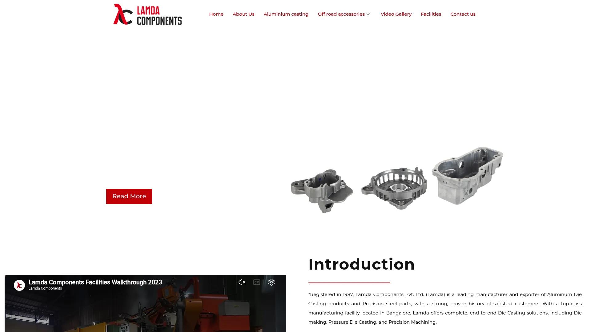
Lamda Components Pvt. Ltd. is a Bangalore-based manufacturer and exporter established in 1987, working in aluminum die casting, precision machining, die making, and off-road vehicle accessories for OEM and industrial customers in domestic and export markets. The combined casting, tooling, and machining vantage point is what allows porosity to be addressed across the full chain rather than at a single stage.
- Die casting components produced on automated machinery from 250 to 800 tons, with auto ladle, auto spray, and auto extractor.
- Complete die casting solution including shot blasting, vibro deburring, resin impregnation, precision machining, leak testing, anodizing, powder coating, and sub-assemblies.
- Tool design and development in-house, linking die making, casting, and machining for cross-functional defect prevention.
- Castings used across fuel injection pumps, alternators and starter motors, electric vehicle motors, hydraulic and pneumatic equipment, off-road products, and the automotive sector.
Talk to our team about your aluminum HPDC parts – Contact us: https://lamdacomponents.com/contact
Frequently asked questions
What causes porosity in aluminum high pressure die casting?
Porosity has two root causes: trapped gas and solidification shrinkage. Gas porosity comes from air entrained during turbulent fill, poor venting, or dissolved hydrogen in the melt. Shrinkage porosity comes from insufficient feeding as the metal contracts during solidification, typically at thick sections, rib junctions, and hot spots.
How do you reduce porosity in HPDC castings?
Reduce porosity with a full-system approach: degas and clean the melt, tune the slow/fast shot and switch-over against venting capacity, design gates, overflows, and venting to evacuate air, apply intensification pressure for feeding, balance die temperature, and verify with X-ray, CT, or leak testing matched to part criticality.
What is HPDC in automotive manufacturing?
HPDC, or high pressure die casting, injects molten aluminum at high speed and pressure into a steel die, then rapidly solidifies and ejects it. In automotive manufacturing it produces high volumes of thin-walled, complex parts – housings, covers, brackets, and structural castings – with good dimensional repeatability and surface quality.
What is the difference between gas porosity and shrinkage porosity?
Gas porosity is caused by entrapped air or precipitated hydrogen and is a cavity-fill and venting problem; the pores often appear more rounded. Shrinkage porosity is caused by inadequate feeding during solidification and is tied to thermal balance and hot spots; the voids are often more irregular or interdendritic.
How does vacuum die casting help reduce porosity?
Vacuum die casting evacuates air from the die cavity before and during fill, reducing entrapped air and improving density. Because it targets gas porosity specifically, it is most justified for leak-tight, structural, or high-integrity parts, and for geometries with long flow lengths, large projected areas, or thin reinforced walls.
Why does machining reveal porosity in die cast aluminum parts?
Machining removes the dense as-cast skin and cuts into subsurface metal, opening voids that were sealed below the surface. On sealing faces, drilled holes, and threaded features, these exposed pores become leak paths or strength defects – which is why a clean as-cast inspection does not guarantee leak-tight performance after machining.
What process parameters most affect porosity in HPDC?
The strongest levers are plunger/injection speed, intensification pressure, die temperature, and melt temperature, supported by vacuum effectiveness, shot-sleeve fill ratio, and switch-over timing. Each acts on one mechanism – speed and venting govern gas porosity, while intensification and thermal balance govern shrinkage – so they must be tuned together, not in isolation.
What are the most common defects in aluminum die cast parts?
Beyond porosity, common defects include cold shuts and misruns from low temperature or incomplete fill, blisters from subsurface gas, soldering from high die temperature, flash from clamping or pressure issues, shrinkage voids from poor feeding, and dimensional variation from thermal instability. Porosity remains one of the most critical defects for automotive integrity.
