
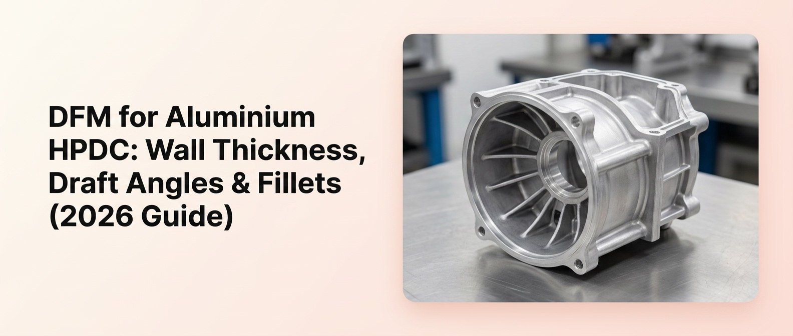
For engineers evaluating aluminum HPDC parts, the geometry decisions you make in CAD determine castability, tooling cost, porosity risk, and how much machining a part needs later. This guide focuses on the three DFM pillars that matter most, wall thickness, draft angles, and fillets, and shows how each connects to metal flow, ejection, and downstream quality.
Design-for-manufacturability (DFM) for aluminum HPDC parts is the practice of shaping geometry, such as wall thickness, draft angles, and fillets, so molten aluminum fills cleanly, solidifies predictably, and ejects without damage. Getting these right before tooling is cut reduces porosity, tooling revisions, and unnecessary machining.
Key takeaways
- Uniform wall section usually matters more than chasing the thinnest possible wall.
- Wall thickness starting ranges depend on alloy, part size, feature depth, and fill path, so values should be confirmed with the foundry.
- Draft angles are essential for die release and directly influence ejection, surface finish, and tool life.
- Fillets and radii improve metal flow, reduce stress concentration, and lower reject risk.
- Poor DFM can increase tooling cost, porosity risk, and downstream machining, and most corrections are cheapest before the tool is cut.
- Lamda Components Pvt. Ltd. combines die making, aluminium die casting, and precision machining, which helps align castability, tooling, and machining decisions before RFQ.
What aluminium HPDC parts are (and where HPDC fits)
High pressure die casting (HPDC) produces aluminum parts by injecting molten metal under high pressure into a hardened steel die, then rapidly solidifying and ejecting the part. Aluminum HPDC parts are cast aluminium components made by forcing molten alloy into a steel die at high pressure, producing thin-wall, complex, high-volume parts with good surface finish and dimensional repeatability. This is the essence of the high pressure die casting process fundamentals.
The process suits geometries where thin walls, complex shapes, and high production volumes come together. HPDC works especially well for:
- Housings, enclosures, and covers
- Brackets and structural, lightweight components
- Heat-management parts where thin walls aid cooling
- Automotive and EV components requiring repeatable dimensions
Lamda’s die castings are used across sectors including fuel injection pumps, alternators and starter motors, electric vehicle motors, textile machinery, hydraulic equipment, off-road products, the automotive sector, LED lights and door closures, electrical and household appliances, pneumatic products, and medical equipment. Each of these families benefits from HPDC’s ability to cast thin, detailed sections at volume rather than machining them from solid. Explore Lamda’s full range of die casting products to see typical component families.
Why DFM matters in aluminium HPDC
DFM in HPDC means designing part geometry so it fills, solidifies, and ejects reliably in a steel die, following established design for manufacturability principles. The core principle is simple: geometry changes are cheapest before tooling is cut. Once a die is machined, correcting a thick section, missing draft, or sharp corner often means reworking hardened steel, which is slow and expensive.
The three DFM pillars map directly to manufacturing outcomes. Wall thickness governs metal flow, cooling time, and porosity. Draft governs ejection, surface drag, and tool wear. Fillets govern flow continuity and stress concentration. Together they drive tooling complexity, cycle time, and how much secondary machining a part needs.
DFM Pro Tip: Uniform wall section usually matters more than chasing the thinnest possible wall. Consistent sections solidify predictably, which is what keeps porosity and distortion low.
Because Lamda combines tool design and development, aluminium die casting, and precision machining, buyers can align castability, tooling, and machining requirements with one supplier rather than splitting them across separate vendors. You can review Lamda’s manufacturing facilities to understand this end-to-end capability.
Wall thickness design rules for aluminium HPDC
Wall thickness is the single most influential geometry decision in HPDC because it controls how metal flows and how heat leaves the part. Many foundries treat around 2.0 mm nominal wall, within a broader 1.0–5.0 mm window, as a reasonable starting point for aluminum HPDC, then adjust for alloy, part size, feature depth, and fill path. Exact values should be confirmed with your supplier for your specific part. See recommended wall thickness ranges for die casting for practical alloy-specific guidance.
What is a uniform wall section?
A uniform wall section means the part maintains a consistent thickness across its main surfaces rather than mixing thick and thin regions. Uniform walls help maintain stable filling and predictable solidification, which reduces the localized cooling differences that cause porosity, sink, and distortion. Where thickness must change, the transition should be gradual rather than a sudden step.
Why thick sections create hot spots and porosity risk
Thick sections hold heat longer than the walls around them, creating thermal hot spots. Because these regions cool and solidify last, they are prone to shrinkage porosity as the metal contracts with no feed path to compensate. Thick zones also extend cooling and cycle time. The usual fix is to core out heavy mass and use ribs to recover stiffness without the bulk.
How wall transitions should be handled
Abrupt thick-to-thin transitions interrupt metal flow and create cooling gradients that produce porosity, distortion, and cosmetic defects. Gradual tapers and generous fillets at the junction let metal flow continuously and cool more evenly. Any change in section should blend smoothly rather than stepping, so the solidification front moves predictably rather than trapping isolated pools of hot metal.
When to use ribs instead of adding wall mass
When a part needs more stiffness, adding ribs is almost always better than thickening the wall. Ribs add structural rigidity without creating the heavy sections that cause hot spots and long cooling times. As a working guideline, keep rib thickness at or below the adjacent wall thickness, and fillet the rib base, to avoid creating a new mass concentration that behaves like a thick section.
| Design feature | Why it matters in HPDC | Risk if ignored | DFM fix |
| Uniform wall section | Stable fill and predictable solidification | Porosity, sink, distortion | Keep sections consistent; blend changes |
| Thick sections | Hold heat, cool last | Shrinkage porosity, hot spots, longer cycle | Core out mass; add ribs |
| Abrupt transitions | Interrupt flow and cooling | Porosity, cosmetic defects | Gradual taper plus fillet |
| Ribs vs added mass | Stiffness without bulk | Excess weight, hot spots | Rib ≤ wall thickness, filleted base |
Did you know: thicker aluminum walls raise cooling and cycle time because heat takes longer to leave the section, so section control is both a quality and a productivity decision.
Draft angle design rules for aluminium HPDC
Draft is the slight taper applied to surfaces in the pull direction so the part releases cleanly from the die. Most design guides start at roughly 1–1.5° of draft on external walls and 2–3° on internal and core surfaces for aluminum HPDC, with extra draft for deep pockets and textured faces. Exact values depend on surface type, depth, texture, and ejection strategy.
Why zero-draft designs create risk
A surface with little or no draft resists release. As the aluminium shrinks onto cores and walls during solidification, insufficient draft leads to ejection problems, drag marks, and accelerated die wear. Deep pockets with low draft are especially prone to galling and stuck parts. Building draft in from the start protects both surface quality and tool life.
How draft needs differ by surface type
Draft requirements change with the finish you want. As-cast surfaces need enough draft to release cleanly. Textured surfaces need more, because the texture itself grips the die, and guides commonly add roughly 1° of extra draft per 0.025–0.05 mm of texture depth. Surfaces that will be machined later can sometimes tolerate less draft, since a machined datum removes the cast surface anyway.
How parting line location changes draft strategy
The parting line, where the two die halves meet, sets the pull direction, and every drafted surface must taper toward its opening half. Choosing the parting line poorly can force undercuts that require side cores, adding tooling complexity and cost. Planning the parting line early lets draft, cosmetics, and flash be managed together rather than fought individually later.
How ejector placement influences draft decisions
Ejector pins push the part off the cores, and where they act interacts with draft. Adequate draft reduces the ejection force needed, which lets pins do their job without marking cosmetic faces or distorting thin walls. Reviewing draft and ejector layout together, from a die-making perspective, helps ensure the part comes out cleanly and repeatably at production speed.
| Surface type | Draft guidance (starting point) | Notes for tooling | Ejection consideration |
| External walls | ~1–1.5° | Toward parting line | Lower force with more draft |
| Internal / core surfaces | ~2–3° | Shrinkage grips cores | Higher risk of stuck parts |
| Textured surfaces | Add draft per texture depth | Texture increases grip | Drag marks if too little |
| To-be-machined faces | Can be less | Datum removes cast surface | Confirm stock allowance |
Fillet and radius design rules for aluminium HPDC
Fillets and radii are the rounded transitions at corners and junctions, and they do far more than soften edges. In aluminum HPDC, fillets improve metal flow, reduce stress concentration, and lower defect risk, so most design guides recommend internal corner radii of roughly 0.5–1.0 mm, increasing toward 1.5–3.0 mm in structural or high-thermal-load areas.
Why sharp corners interrupt metal flow
Sharp internal corners disrupt the flow of molten aluminium, creating turbulence and incomplete fill. They are also stress concentrators, so the same corner that fills poorly is also the point most likely to crack in service. Rounding the corner restores flow continuity and spreads stress over a larger area, improving both castability and durability.
How fillets support filling and solidification
A well-radiused corner gives metal a smooth path around the junction, which reduces trapped air and helps the section solidify evenly. This lowers the chance of localized porosity and cold shut at corners. Consistent radii also keep wall thickness more uniform through the transition, which reinforces the same solidification stability that section control aims for.
Where minimum radii matter most
Radii matter most at rib bases, boss transitions, and wall junctions, exactly where sharp corners would otherwise create both flow disruption and stress. A common rule of thumb is a fillet radius of about half the wall thickness at rib and boss bases to reduce sink and hot spots. Corners near heavy sections or gates typically warrant larger radii.
How fillets affect machining and cosmetic finish
Fillets influence downstream work as well. A cleanly radiused casting is easier to finish and presents fewer stress risers on cosmetic faces. Where a corner will later be machined, the cast radius and the machined feature must be planned together so tooling can reach the corner without leaving a witness step. This is where casting and precision machining planning together pays off.
| Corner / junction type | Flow impact | Likely defect | Recommended radius approach |
| Sharp internal corner | Turbulent, incomplete fill | Cold shut, cracks | Add fillet, ~0.5 mm minimum |
| Rib base | Local mass at junction | Sink, hot spot | Fillet ~½ wall thickness |
| Boss transition | Flow interruption | Porosity, sink | Filleted heel, supported |
| Structural / high-load corner | Stress concentration | Cracking | 1.5–3.0 mm radius |
Did you know: sharp corners in castings act as stress concentrators, raising local stress above a rounded corner, which makes fillet design a durability decision as much as a fill decision.
How wall thickness, draft and fillets work together
The three pillars are not independent. Wall thickness sets the fill path and solidification sequence; fillets keep that path continuous around corners; draft ensures the solidified part releases without damage. A change to one usually affects the others, adding a fillet at a rib base, for example, slightly changes local section thickness and can influence cooling.
Read together, they determine metal flow, solidification order, ejection behavior, and overall tooling complexity:
- Uniform walls plus generous fillets give the cleanest, most predictable fill.
- Adequate draft on every drafted surface protects that geometry during ejection.
- Poor coordination among the three produces many preventable defects.
Buyer Warning: A geometry can be castable but still be expensive to tool or unstable to machine. Reviewing all three pillars together, rather than one at a time, is what keeps a part both manufacturable and economical.
Related DFM features: ribs, bosses, parting line and machining allowance
Beyond the three core pillars, a handful of secondary features decide whether a good concept becomes a clean production part. These are often treated generically, but they reward the same section-and-transition discipline applied above.
Designing bosses on thin walls
Bosses concentrate mass, so an unsupported boss on a thin wall behaves like a thick section, inviting sink marks, porosity, and dimensional instability. Keep boss walls close to the adjacent wall thickness, add fillets at the base, and support taller bosses with ribs. Avoid abrupt boss bases dropped straight onto thin walls without any supporting geometry.
Ribs for stiffness without excess mass
Ribs are the preferred way to add rigidity without heavy sections. Keep rib thickness at or below the main wall thickness so the rib does not become a hot spot, and fillet the rib base to smooth flow. Well-proportioned ribs let a part stay thin and light while meeting stiffness targets.
Parting line strategy for cosmetics and manufacturability
Parting line placement affects where flash forms, where cosmetic seams appear, which surfaces stay as-cast versus machined, and how draft must be applied. Placing the parting line thoughtfully keeps flash easy to trim, keeps seams off show surfaces, and keeps sealing faces clear of ejector marks. It is best decided early, alongside draft and cosmetics.
As-cast vs machined: leaving material intelligently
Not every surface should be machined, and not every surface can be left as-cast. Sealing faces, precision bores, and datum-critical features generally need machining, so intentional stock must be left on them. But heavy “just in case” stock adds cycle time and can expose subsurface porosity. The goal is consistent stock tied to the datum scheme and the foundry’s process capability. Confirm machining stock values with your supplier for your part.
Machining Note: A part can be near-net shape and still need intentional stock on sealing faces, bores, or critical datums. Deep cuts into a casting can expose porosity, so machining strategy should be set during design, not after.
Lamda’s process capabilities span tool design and development, aluminium die casting, shot blasting, vibro deburring, resin impregnation, precision machining, leak testing, powder coating and painting, and sub-assemblies, which allows as-cast versus machined decisions to be considered with the finishing route already in view.
Common defects tied to poor HPDC part design
Many HPDC defects trace directly back to geometry choices, which is why DFM is a quality tool, not just a cost tool. Common design-driven defects include shrinkage porosity from thick sections, drag marks and ejection damage from insufficient draft, fill and cracking problems from sharp corners, and sink or porosity from unsupported bosses. Each has a clear geometric fix.
| Geometry issue | Likely defect | Root cause | Design change |
| Thick sections | Shrinkage porosity | Hot spots, no feed path | Core out mass, add ribs |
| Insufficient draft | Drag marks, ejection damage | Poor release | Add draft per surface type |
| Sharp corners | Poor fill, cracking | Flow disruption, stress riser | Add fillets |
| Unsupported bosses | Sink, local porosity | Mass concentration | Support and fillet, redistribute |
| Abrupt wall transitions | Porosity, distortion | Cooling gradients, trapped air | Gradual taper, fillet |
Wall transitions and fill path also govern air-entrapment sensitivity. Abrupt changes create pockets where air can be trapped ahead of the metal front, so gradual transitions and thoughtful section control reduce that risk before any process controls are applied.
Did you know: aluminum die casting scrap rates rise with part complexity and weak DFM, which is why correcting geometry before tool cut is a high-leverage way to protect yield.
HPDC vs LPDC and gravity die casting for difficult geometries
Choosing a casting process is a geometry decision first and an economics decision second. HPDC is the right answer when you have thin walls, complex detail, and enough volume to amortize tooling. Other routes become attractive when those conditions do not hold.
| Design factor | HPDC | LPDC | Gravity die casting |
| Wall thickness | Thin walls, complex detail | Thicker, sound sections | Thicker walls, simpler detail |
| Fill behavior | High pressure, fast | Low turbulence | Slower, gravity fed |
| Volume fit | High volume | Medium volume | Low to medium volume |
| Tooling cost | Higher | Moderate | Lower |
| Best for | Housings, covers, thin-wall parts | Structural, integrity-critical parts | Simpler geometry, moderate runs |
HPDC is usually the wrong process when:
- Volumes are too low to justify hardened steel tooling.
- Sections are very thick or highly imbalanced.
- The part has difficult undercuts that force complex side actions.
- Integrity demands outweigh HPDC’s economic advantage, favoring LPDC or gravity casting.
Framing the choice around geometry first keeps the conversation focused on whether the part fits the process, not just on price.
How to review an aluminium HPDC part before RFQ (buyer and supplier checklist)
The cheapest revisions happen before you send a part out for quote. A short, disciplined review catches most manufacturability problems while they are still CAD edits rather than tooling changes.
7 DFM checks before sending an aluminium HPDC part for quote
- Uniform wall section reviewed and heavy mass cored out.
- Draft applied per surface type and pull direction.
- Fillets added to internal corners and junctions.
- Ribs and bosses supported and correctly proportioned.
- Parting line planned for cosmetics, flash, and machining.
- As-cast versus machined features clearly identified.
- Tolerances set realistically for as-cast versus machined surfaces.
What CAD and DFM data to share for a fast manufacturability review
- 3D CAD model in a neutral or native format.
- A 2D drawing with critical dimensions, tolerances, and datums.
- Alloy and any surface-finish or coating requirements.
- Functional notes: sealing faces, mating features, pressure or leak requirements.
- Expected annual volume and target application.
What to align with Lamda before finalizing an HPDC geometry
When discussing an HPDC part with Lamda, it helps to share the geometry, critical features, alloy, and machining requirements early. Lamda’s capabilities include tool design and development, aluminium die casting, and precision machining, so casting and finishing requirements can be aligned with one supplier. Learn more about Lamda’s experience and expertise as a die casting manufacturer.
Send your part drawing for a manufacturability review. Contact us to discuss your aluminum HPDC part with Lamda’s engineering team.
Frequently asked questions
What is the ideal wall thickness for aluminum HPDC parts?
There is no single ideal value. Many foundries start around 2.0 mm nominal within a broader 1.0–5.0 mm window, then adjust for alloy, part size, feature depth, and fill path. Confirm the right starting range with your supplier for your specific geometry rather than treating any number as absolute.
Why is uniform wall thickness important in HPDC parts?
Uniform wall thickness promotes stable filling and predictable solidification. Consistent sections cool at similar rates, which lowers the risk of hot spots, shrinkage porosity, sink, and distortion. Where thickness must change, gradual transitions keep the solidification front moving evenly and prevent isolated pools of hot metal.
How much draft angle is needed for aluminium die casting?
Draft varies by surface. Common starting points are roughly 1–1.5° on external walls and 2–3° on internal and core surfaces, with extra draft for deep pockets and textured faces. The exact requirement depends on surface type, depth, texture, and ejection strategy, so confirm values with your supplier.
What happens if an HPDC part has too little draft?
Insufficient draft causes the part to grip the die as it shrinks, leading to ejection problems, drag marks on surfaces, and accelerated die wear. Deep, low-draft pockets are especially prone to galling and stuck parts. Adding adequate draft protects both surface quality and long-term tool life.
Why are fillets important in aluminum HPDC design?
Fillets improve metal flow around corners, reduce stress concentration, and lower defect risk. Sharp internal corners disrupt fill and act as stress risers where cracks start. Rounded transitions restore flow continuity, help sections solidify evenly, and improve both castability and in-service durability.
Can I reduce weight by thinning walls without increasing defect risk?
Often yes, but within limits. Thin walls reduce weight and cooling time but increase fill sensitivity, so they demand uniform sections, good fillets, and a well-planned fill path. Combining modest wall thickness with ribs for stiffness is usually safer than pushing every wall to the thinnest possible dimension.
When should I add ribs instead of increasing wall thickness?
Add ribs when you need more stiffness without the penalties of a thick section. Thickening walls creates hot spots, shrinkage porosity, and longer cooling times. Ribs provide rigidity while keeping the part light, provided rib thickness stays at or below the adjacent wall and the base is filleted.
Can an HPDC part have zero draft on critical surfaces?
True zero draft is risky on as-cast surfaces because the part must release from the die. Surfaces that will be machined afterward can sometimes tolerate very little draft, since machining removes the cast face. For as-cast critical surfaces, plan draft and ejection with your supplier rather than assuming zero.
What tolerances are realistic as-cast versus after machining?
As-cast HPDC handles moderate tolerances on general surfaces well, but tight-tolerance bores, sealing faces, and datum-critical features usually require machining. A good practice is to reference GD&T from a cast-in datum and machine only where function demands it. Confirm specific tolerance bands with your supplier by feature and alloy.
When should an aluminium HPDC part be machined after casting?
Machine features that need precision beyond as-cast capability, such as sealing faces, precision bores, and datum-critical surfaces. Leave intentional, consistent stock on these, sized to process capability and porosity risk. Avoid heavy stock everywhere, since deep cuts can expose subsurface porosity and add unnecessary cycle time.
How do you reduce porosity in aluminum HPDC parts?
Start with geometry: keep walls uniform, core out thick sections, use gradual transitions, add fillets, and support bosses to avoid mass concentrations. These changes reduce hot spots, trapped air, and shrinkage. Because porosity often has a geometric root, fixing the design before tool cut is a high-leverage step.
When is HPDC the wrong process for an aluminum part?
HPDC is a poor fit when volumes are too low to justify hardened tooling, when sections are very thick or badly imbalanced, when difficult undercuts force complex tooling, or when integrity demands favor low-pressure or gravity casting. In those cases, LPDC, gravity die casting, machining, or fabrication may suit the geometry better.
